| Non-Rationalised NCERT Books Solution | ||||||
|---|---|---|---|---|---|---|
| 6th | 7th | 8th | 9th | 10th | 11th | 12th |
| Content On This Page | ||
|---|---|---|
| Exercise 15.1 | Example 1 (Before Exercise 15.2) | Exercise 15.2 |
| Example 2 (Before Exercise 15.3) | Exercise 15.3 | Exercise 15.4 |
Chapter 15 Visualising Solid Shapes
Welcome to the solutions guide for Chapter 15: Visualising Solid Shapes. This chapter serves as a fascinating bridge between the flat, two-dimensional (2D) world of plane geometry we often study on paper and the tangible, three-dimensional (3D) world we inhabit. Our ability to understand, interpret, and represent solid objects is a crucial aspect of spatial reasoning, essential not only for further studies in mathematics, science, and technology but also fundamental to fields like architecture, engineering, art, design, medicine (interpreting scans), and even everyday tasks like assembling furniture or packing boxes. This chapter focuses on developing the vital skill of visualisation – the ability to mentally manipulate and perceive 3D objects and their properties, even when presented in a 2D format.
The solutions provided offer clear guidance and practical techniques to enhance these spatial skills. The journey begins by reinforcing the fundamental distinction between plane figures (like squares, circles, triangles – having only length and breadth) and solid shapes (like cubes, spheres, cones – possessing length, breadth, and height/depth). A key method for understanding the construction of 3D shapes from 2D surfaces is through Nets.
- A net is a 2D pattern that can be folded along its edges to form a specific 3D solid without any overlaps.
- Solutions explore various possible nets for common solids such as cubes, cuboids, cylinders, cones, and various types of pyramids (e.g., square-based, triangular-based).
- Exercises guide students in identifying whether a given 2D net will correctly fold into the intended solid, requiring careful mental folding or visualization.
Representing 3D objects on flat 2D paper presents a unique challenge. The solutions introduce two primary sketching techniques:
- Oblique Sketches: These are relatively simple to draw, often showing the front face true to shape and size, with depth represented by parallel lines drawn typically at a $45^\circ$ angle. However, oblique sketches may not maintain accurate proportions for lengths going 'into' the page.
- Isometric Sketches: Drawn on special isometric dot paper, these sketches provide a more realistic representation where measurements along all three axes (length, width, height) are drawn to scale, offering a better sense of proportion and perspective. Solutions provide step-by-step guidance for creating both sketch types, particularly for cuboids.
Another critical aspect of spatial visualization is perceiving an object from different perspectives. The solutions cover:
- Multiple Views: Understanding and drawing the front view, side view (usually left or right), and top view of given 3D objects, which might be complex arrangements of cubes or everyday items. This skill is fundamental in technical drawing and design.
- Slicing Solids: Exploring what happens when a solid shape is cut. The 2D shape formed by the surface of the cut is called the cross-section. Solutions illustrate examples, such as the circular cross-section obtained from a horizontal cut of a cylinder or cone, or the rectangular cross-section from a vertical cut of a cube parallel to a face.
Finally, the chapter reinforces the basic components of polyhedrons (solids with flat faces, straight edges, and sharp corners or vertices):
- Identifying and counting the number of Faces (F) - the flat polygonal surfaces.
- Identifying and counting the number of Edges (E) - the line segments where two faces meet.
- Identifying and counting the number of Vertices (V) - the points where three or more edges meet.
- The solutions might introduce or verify Euler's Formula for polyhedrons, a remarkable relationship connecting these three components: $F + V - E = 2$. This formula holds true for simple, convex polyhedrons and provides a way to check counts.
Collectively, these activities and explanations aim to significantly strengthen students' ability to visualize, interpret, and represent the three-dimensional world around them.
Exercise 15.1
Question 1. Identify the nets which can be used to make cubes (cut out copies of the nets and try it):
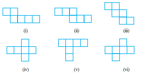
Answer:
A net is a two-dimensional shape that can be folded to form a three-dimensional object. To determine if a net can form a cube, we must visualize folding its 6 squares. The squares must form the six faces of a cube without any overlap and without leaving any gaps.
(i)
This net has a horizontal row of four squares. Let's imagine folding this row to form four sides of a cube. The two additional squares are attached to the top edges of two adjacent squares in the row. When folded, these two squares will attempt to cover the same face (the top face), causing an overlap. Therefore, this net cannot form a cube.
(ii)
This net can be folded into a cube. If you consider the third square from the left as the base, the squares around it can be folded up to form the sides and the top of the cube without any overlap. Therefore, this net can form a cube.
(iii)
This net can be folded to form a cube. By taking one of the central squares as the base, the other five squares can be folded around it to form the sides and the top, completing the cube shape. Therefore, this net can form a cube.
(iv)
This is a standard net for a cube. The central square can be the base. The four squares attached to its sides fold up to become the walls. The final square folds over to become the top lid. Therefore, this net can form a cube.
(v)
This net has a horizontal row of four squares. If we try to fold this row to make the sides of the cube, we find that the two squares attached below will overlap. One will form the bottom face, but the other will have nowhere to go without overlapping another face. Therefore, this net cannot form a cube.
(vi)
This net can be correctly folded into a cube. If you take the square at the top of the 'T' junction as the base, the other squares will fold to form the sides and the top without any conflict. Therefore, this net can form a cube.
In conclusion, the nets which can be used to make cubes are (ii), (iii), (iv), and (vi).
Question 2. Dice are cubes with dots on each face. Opposite faces of a die always have a total of seven dots on them.
Here are two nets to make dice (cubes); the numbers inserted in each square indicatethe number of dots in that box.

Insert suitable numbers in the blanks, remembering that the number on the opposite faces should total to 7.
Answer:
The fundamental rule for a standard die is that the sum of the numbers on opposite faces always equals 7. The pairs of opposite numbers are:
- 1 and 6
- 2 and 5
- 3 and 4
We will use this rule to fill in the blank faces on the given nets.
For the first net:
By visualizing how this net folds into a cube, we can determine the opposite faces. When folded along the horizontal strip of four squares:
- The face numbered '4' will be opposite to the second square from the left.
- The face numbered '5' will be opposite to the square above the strip.
- The face numbered '6' will be opposite to the first square from the left.
Now we can calculate the numbers for the blank faces:
- The face opposite '4' should be $7 - 4 = 3$.
- The face opposite '5' should be $7 - 5 = 2$.
- The face opposite '6' should be $7 - 6 = 1$.
The completed net is:
For the second net:
By folding this net, we find the following opposite pairs:
- The face numbered '1' will be opposite to the third face in the central column.
- The face numbered '2' will be opposite to the second face in the first column.
- The face numbered '3' will be opposite to the second face in the second column.
Now we calculate the missing numbers:
- The face opposite '1' should be $7 - 1 = 6$.
- The face opposite '2' should be $7 - 2 = 5$.
- The face opposite '3' should be $7 - 3 = 4$.
The completed net is:
Question 3. Can this be a net for a die? Explain your answer.
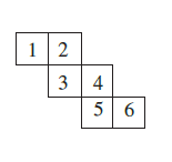
Answer:
No, this cannot be a net for a standard die.
Explanation:
The primary rule for a standard die is that the sum of the numbers on opposite faces must always be 7. The required pairs of opposite faces are:
- 1 and 6 (Sum = 7)
- 2 and 5 (Sum = 7)
- 3 and 4 (Sum = 7)
Now, let's analyze the given net to see which faces would be opposite each other if it were folded into a cube.
By visualizing the folding process, we can identify the pairs of faces that will end up on opposite sides:
- The face with the number 1 will be opposite the face with the number 5.
- The face with the number 2 will be opposite the face with the number 6.
- The face with the number 3 will be opposite the face with the number 4.
Let's check if the sum of these opposite faces is 7:
- For the pair (1, 5): $1 + 5 = 6$
- For the pair (2, 6): $2 + 6 = 8$
- For the pair (3, 4): $3 + 4 = 7$
Conclusion:
While one pair of opposite faces (3 and 4) correctly sums to 7, the other two pairs do not. The pair (1, 5) sums to 6, and the pair (2, 6) sums to 8.
Since the condition that all pairs of opposite faces must sum to 7 is not met, this net cannot form a standard die.
Question 4. Here is an incomplete net for making a cube. Complete it in at least two different ways. Remember that a cube has six faces. How many are there in the net here? (Give two separate diagrams. If you like, you may use a squared sheet for easy manipulation.)
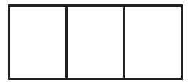
Answer:
The given incomplete net has 3 square faces. A cube has a total of 6 faces. Therefore, we need to add 3 more square faces to the net to make it complete.
This can be done in several different ways. Below are two possible ways to complete the net.
First Way:
We can add one square above the middle square and two squares below the middle square of the given strip. This creates a valid net that can be folded into a cube.
Second Way:
We can add the three required squares to one end of the strip, forming a T-shape. This configuration also creates a valid net for a cube.
Question 5. Match the nets with appropriate solids:
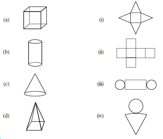
Answer:
To match the solids with their appropriate nets, we need to analyze the faces and surfaces of each 3D shape and find the 2D layout that can be folded to form it.
(a) Cube ↔ (ii) Net of squares
Solid (a) is a cube. A cube is a three-dimensional solid with six equal square faces. Net (ii) is composed of six squares arranged in a cross shape. This is a standard net that can be folded up to form the six faces of a cube.
(b) Cylinder ↔ (iii) Net of rectangle and circles
Solid (b) is a cylinder. A cylinder has two circular bases (a top and a bottom) and a single curved surface. When this curved surface is unrolled, it forms a rectangle. Net (iii) shows a rectangle with two circles attached to its opposite sides, which perfectly represents the unrolled parts of a cylinder.
(c) Cone ↔ (iv) Net of circle and sector
Solid (c) is a cone. A cone has a circular base and a curved surface that tapers to a single point (the apex). The net for a cone consists of a circle (for the base) and a sector of a larger circle (for the curved surface). Net (iv) shows a circle and a shape representing this unrolled curved surface.
(d) Square Pyramid ↔ (i) Net of square and triangles
Solid (d) is a square pyramid. This pyramid has a square base and four triangular faces that meet at a common apex. Net (i) shows a central square with four triangles attached to each of its sides. When folded, these triangles will meet at a point to form the pyramid on its square base.
The correct matches are summarized below:
| Solid | Net |
| (a) | (ii) |
| (b) | (iii) |
| (c) | (iv) |
| (d) | (i) |
Example 1 (Before Exercise 15.2)
Example 1. Here is an oblique sketch of a cuboid [Fig 15.14(i)].
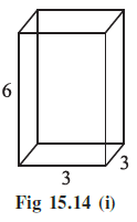
Draw an isometric sketch that matches this drawing.
Answer:
An oblique sketch is a way of drawing a 3D object where the front face is drawn as if you are looking at it head-on, and the receding sides are drawn at an angle. The lengths on the receding sides are not always drawn to scale.
An isometric sketch, on the other hand, is drawn on isometric dot paper or by using specific angles, where the object is viewed from a corner. All measurements are kept in their true proportions. Vertical lines are drawn vertically, and horizontal lines are drawn at an angle of $30^\circ$ to the horizontal line.
Given Dimensions:
From the oblique sketch provided, the dimensions of the cuboid are:
- Length = 3 units
- Width = 3 units
- Height = 6 units
Steps to draw the Isometric Sketch:
1. First, draw a line segment representing the length (3 units) at an angle of $30^\circ$ to the horizontal. From the same starting point, draw another line segment representing the width (also 3 units) at an angle of $30^\circ$ on the other side.
2. From the corners of the base, draw vertical lines upwards to represent the height (6 units).
3. Connect the top ends of the vertical lines to complete the top face of the cuboid. These lines should be parallel to the base lines.
4. This will result in an isometric sketch where all dimensions are accurately represented.
The resulting Isometric Sketch is as follows:
Exercise 15.2
Question 1. Use isometric dot paper and make an isometric sketch for each one of the given shapes:
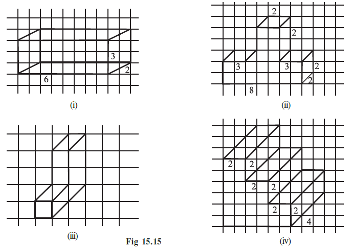
Answer:
An isometric sketch is a 3D representation of an object on a 2D surface. To create these sketches, we interpret the given oblique drawings on the square grid to understand the object's dimensions (length, width, and height) and then draw them on isometric dot paper.
(i)
To create the isometric sketch for the first figure, we first need to interpret the dimensions from the given oblique sketch and its labels:
- The label '6' on the bottom edge indicates the total length of the shape is 6 units.
- The label '3' on the vertical edge on the right indicates the total height of that section is 3 units.
- The label '2' on the top-right horizontal edge indicates the length of that upper section is 2 units.
- From the grid lines, we can see that the height of the main lower part of the object is 2 units.
From these dimensions, we can understand the figure as a composite solid made of two attached cuboids:
- Base Cuboid: It has a length of 6 units and a height of 2 units.
- Top Cuboid: It sits on top of the base. Its height is the total height minus the base height: $3 - 2 = 1$ unit. Its length is given as 2 units.
- Width (Depth): The width is not explicitly labeled, but the parallel slanted lines suggest a uniform width for the entire object. A width of 2 units is a reasonable interpretation that fits the visual proportions.
So, we will draw a base cuboid of 6 × 2 × 2 (Length × Width × Height) with a smaller cuboid of 2 × 2 × 1 on top of its right end. The resulting isometric sketch is shown below.
(ii)
To create the isometric sketch for the second figure, we analyze its dimensions from the oblique drawing:
- The label '8' at the bottom indicates a total length of 8 units.
- The width (depth) is uniform, suggested by the slanted lines to be 2 units.
- The structure's height varies. The main body has a height of 2 units.
- There is a triangular prism-like peak in the middle. The label '2' on its top edge indicates its length is 2 units. This peak rises from the 2-unit height level to a maximum height of 4 units (as seen by counting grid lines).
The shape can be constructed as follows:
- Draw a base cuboid with dimensions 8 × 2 × 2 (Length × Width × Height).
- On top of this cuboid, find the middle section which has a length of 2 units (from the 3-unit mark to the 5-unit mark along the length).
- On this middle section, draw a triangular prism with a base of 2 × 2 and a height of 2 units. This will create the peak that reaches a total height of 4 units.
The resulting isometric sketch accurately represents this multi-level structure.
(iii)
The third figure is a block in the shape of the letter 'C'. We determine its dimensions by counting the squares on the grid in the oblique sketch:
- The total height is 4 units.
- The total length (or horizontal extent) is 3 units.
- The thickness of the arms and the back of the 'C' is 1 unit.
- The width (depth) is suggested by the slanted lines to be 2 units.
To draw the isometric sketch:
- Start by drawing the back vertical part as a cuboid with dimensions 1 × 2 × 4 (Length × Width × Height).
- Attach the top arm, which is a cuboid of 3 × 2 × 1, to the top of the back part.
- Attach the bottom arm, also a cuboid of 3 × 2 × 1, to the bottom of the back part.
This construction creates the 3D 'C' shape.
(iv)
The fourth figure is a staircase-like structure. The labels '2' on multiple edges strongly suggest that the shape is built from identical blocks.
- The basic building block is a cube with side length 2 units (2 × 2 × 2).
- The overall structure consists of three of these cubes arranged in an ascending, staggered pattern.
To draw the isometric sketch:
- First, draw one 2 × 2 × 2 cube on the base level.
- Next, draw a second identical cube. Position it so it is adjacent to the first cube, but shifted upwards and to one side, forming the next step. For example, its front-bottom-right corner could align with the first cube's front-top-left corner.
- Finally, draw the third cube in the same manner, stepping up from the second cube.
This creates a three-step staircase, with each step being a 2x2x2 cube.
Question 2. The dimensions of a cuboid are 5 cm, 3 cm and 2 cm. Draw three different isometric sketches of this cuboid.
Answer:
Given
A cuboid with dimensions 5 cm, 3 cm, and 2 cm.
To Do
Draw three different isometric sketches of this cuboid.
Solution
An isometric sketch shows three faces of a cuboid. Different sketches can be obtained by changing the orientation, i.e., choosing different dimensions for the length, width (depth), and height as projected onto the isometric axes.
The three different orientations are shown below:
Sketch 1: Dimensions (Length = 5 cm, Width = 3 cm, Height = 2 cm)
In this orientation, the cuboid is resting on its 5 cm by 3 cm face.
Sketch 2: Dimensions (Length = 5 cm, Width = 2 cm, Height = 3 cm)
In this orientation, the cuboid is resting on its 5 cm by 2 cm face.
Sketch 3: Dimensions (Length = 3 cm, Width = 2 cm, Height = 5 cm)
In this orientation, the cuboid is standing tall, resting on its 3 cm by 2 cm face.
Question 3. Three cubes each with 2 cm edge are placed side by side to form a cuboid. Sketch an oblique or isometric sketch of this cuboid.
Answer:
Given
Three cubes, each with an edge length of 2 cm, are placed side by side.
To Do
Sketch an oblique or isometric representation of the cuboid formed.
Solution
1. Determine the dimensions of the resulting cuboid:
- When three cubes of edge 2 cm are placed side by side, they form a longer cuboid.
- The length of the cuboid will be the sum of the lengths of the three cubes: $2 \text{ cm} + 2 \text{ cm} + 2 \text{ cm} = 6 \text{ cm}$.
- The width (or depth) of the cuboid will be the same as the width of one cube: $2 \text{ cm}$.
- The height of the cuboid will be the same as the height of one cube: $2 \text{ cm}$.
So, the dimensions of the resulting cuboid are $6 \text{ cm} \times 2 \text{ cm} \times 2 \text{ cm}$.
2. Oblique Sketch of the Cuboid:
An oblique sketch shows the front face true to shape, and the depth lines are drawn parallel at an angle (usually 45°).
3. Isometric Sketch of the Cuboid:
An isometric sketch represents the cuboid on isometric dot paper, maintaining proportional lengths along the isometric axes.
Question 4. Make an oblique sketch for each one of the given isometric shapes:
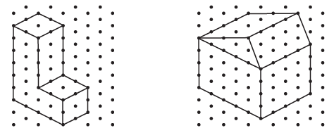
Answer:
An oblique sketch is a way to represent a 3D object on a 2D surface. To convert an isometric sketch to an oblique sketch, we first draw the front face of the object with its true shape and dimensions. Then, we draw the receding edges (representing depth) as parallel lines, typically at a $45^\circ$ angle from the horizontal. The lengths of these receding edges can be drawn to scale or foreshortened (often drawn to half the actual length) to avoid distortion.
(i) Oblique Sketch for the L-shaped block:
First, we determine the dimensions of the L-shaped block from the isometric sketch by counting the units between the dots:
- The front face is an L-shape.
- The overall height of this L-shape is 5 units.
- The overall length of this L-shape is 3 units.
- The vertical arm is 2 units wide.
- The horizontal arm is 2 units high.
- The entire object has a uniform depth (width) of 2 units.
To draw the oblique sketch:
1. Draw the front L-shaped face with its true dimensions (5 units high, 3 units long, with arms of 2 units thickness/height).
2. From each vertex of the front face, draw parallel lines backwards at a $45^\circ$ angle to represent the depth of 2 units.
3. Connect the ends of these receding lines to complete the back face of the block.
The resulting oblique sketch is shown below:
(ii) Oblique Sketch for the House-shaped block:
First, we determine the dimensions of the house-shaped block from the isometric sketch:
- The base is a cuboid with length 5 units, width (depth) 3 units, and height 3 units.
- The roof is a triangular prism that sits on top of the cuboid. The height of the roof from the top of the cuboid to the ridge is 2 units.
- The total height of the structure is $3 + 2 = 5$ units.
To draw the oblique sketch:
1. Draw the front face of the house. This face is a pentagon, which consists of a 5-unit by 3-unit rectangle at the bottom and an isosceles triangle on top of it with a base of 5 units and a height of 2 units.
2. From each vertex of this front face, draw parallel lines backwards at a $45^\circ$ angle to represent the width of 3 units.
3. Connect the ends of these receding lines to form the back face of the house, which will be parallel to the front face.
The resulting oblique sketch is shown below:
Question 5. Give (i) an oblique sketch and (ii) an isometric sketch for each of the following:
(a) A cuboid of dimensions 5 cm, 3 cm and 2 cm. (Is your sketch unique?)
(b) A cube with an edge 4 cm long.
An isometric sheet is attached at the end of the book. You could try to make on it some cubes or cuboids of dimensions specified by your friend.
Answer:
(a) A cuboid of dimensions 5 cm, 3 cm and 2 cm.
(i) Oblique sketch of the cuboid
To create an oblique sketch, we draw the front face with its true dimensions and then draw the receding edges at an angle (usually $45^\circ$).
Steps:
- Draw the front face as a rectangle. Let's choose the 5 cm × 2 cm face.
- From each vertex of this rectangle, draw parallel lines going backwards at a $45^\circ$ angle. These lines represent the width (3 cm).
- Connect the ends of these receding lines to form the back face.
(ii) Isometric sketch of the cuboid
To create an isometric sketch, we draw the dimensions along three axes that are $120^\circ$ apart. Vertical lines remain vertical, and horizontal lines are drawn at $30^\circ$ to the horizontal base line.
Steps:
- Let the dimensions be Length = 5 cm, Width = 3 cm, and Height = 2 cm.
- Draw a vertical line segment for the height (2 cm).
- From the base of the height line, draw lines for the length (5 cm) and width (3 cm) at $30^\circ$ angles.
- Complete the base and top faces by drawing parallel lines.
Is your sketch unique?
No, the sketch is not unique. The sketches can be drawn in multiple ways by changing the orientation of the cuboid. For instance, we could have chosen the 3 cm × 2 cm face as the front face for the oblique sketch, or we could have assigned the height to be 5 cm in the isometric sketch. Each orientation results in a different-looking sketch of the same cuboid.
(b) A cube with an edge 4 cm long.
(i) Oblique sketch of the cube
A cube has six identical square faces.
Steps:
- Draw the front face as a 4 cm × 4 cm square.
- From each vertex, draw parallel receding lines at a $45^\circ$ angle to represent the depth of 4 cm.
- Connect the ends of these lines to form the back square.
(ii) Isometric sketch of the cube
All edges are 4 cm long and are drawn to scale along the isometric axes.
Steps:
- Draw a vertical line of 4 cm for the height.
- From the base of this line, draw two lines of 4 cm each at $30^\circ$ angles to the horizontal to represent length and width.
- Complete the cube by drawing the remaining edges parallel to these three initial edges.
Example 2 (Before Exercise 15.3)
Example 2. If two cubes of dimensions 2 cm by 2cm by 2cm are placed side by side, what would the dimensions of the resulting cuboid be?
Answer:
Given:
We are given two identical cubes. The dimensions of each cube are 2 cm by 2 cm by 2 cm.
This means for each cube:
- Length = 2 cm
- Width (or Breadth) = 2 cm
- Height = 2 cm
To Find:
The dimensions of the new cuboid formed when these two cubes are placed side by side.
Solution:
When the two cubes are placed side by side, they are joined along one of their faces. Let's analyze how this affects the overall dimensions of the resulting solid.
1. Length:
The length of the new shape is the sum of the lengths of the two individual cubes because they are placed along this dimension.
New Length = Length of Cube 1 + Length of Cube 2
New Length = $2 \text{ cm} + 2 \text{ cm} = 4 \text{ cm}$
2. Width (Breadth):
The width of the resulting cuboid remains the same as the width of a single cube because the cubes are not stacked in that direction.
New Width = 2 cm
3. Height:
Similarly, the height of the resulting cuboid remains the same as the height of a single cube because they are not stacked on top of each other.
New Height = 2 cm
Conclusion:
The dimensions of the resulting cuboid are 4 cm, 2 cm, and 2 cm.
Exercise 15.3
Question 1. What cross-sections do you get when you give a
(i) vertical cut
(ii) horizontal cut
to the following solids?
(a) A brick
(b) A round apple
(c) A die
(d) A circular pipe
(e) An ice cream cone
Answer:
A cross-section is the 2D shape that is exposed when a 3D solid is sliced through. The shape of the cross-section depends on the shape of the solid and the angle of the cut.
(a) A brick
A brick has the shape of a cuboid.
(i) Vertical Cut: When a brick is cut vertically (perpendicular to its base), the exposed face is a rectangle.
(ii) Horizontal Cut: When a brick is cut horizontally (parallel to its base), the exposed face is also a rectangle.
(b) A round apple
A round apple has the shape of a sphere.
(i) Vertical Cut: When a round apple is cut vertically, the cross-section is a circle.
(ii) Horizontal Cut: When a round apple is cut horizontally, the cross-section is also a circle.
(c) A die
A die has the shape of a cube.
(i) Vertical Cut: When a die is cut vertically, the cross-section is a square.
(ii) Horizontal Cut: When a die is cut horizontally, the cross-section is also a square.
(d) A circular pipe
A circular pipe has the shape of a cylinder.
(i) Vertical Cut: When a circular pipe is cut vertically along its length, the cross-section is a rectangle.
(ii) Horizontal Cut: When a circular pipe is cut horizontally across its length, the cross-section is a circle.
(e) An ice cream cone
An ice cream cone has the shape of a cone.
(i) Vertical Cut: When an ice cream cone is cut vertically through its apex (the tip), the cross-section is a triangle.
(ii) Horizontal Cut: When an ice cream cone is cut horizontally, the cross-section is a circle.
Here is a summary of the results:
| Solid | (i) Vertical Cut Cross-section | (ii) Horizontal Cut Cross-section |
| A brick | Rectangle | Rectangle |
| A round apple | Circle | Circle |
| A die | Square | Square |
| A circular pipe | Rectangle | Circle |
| An ice cream cone | Triangle | Circle |
Exercise 15.4
Question 1. A bulb is kept burning just right above the following solids. Name the shape of the shadows obtained in each case. Attempt to give a rough sketch of the shadow. (You may try to experiment first and then answer these questions).
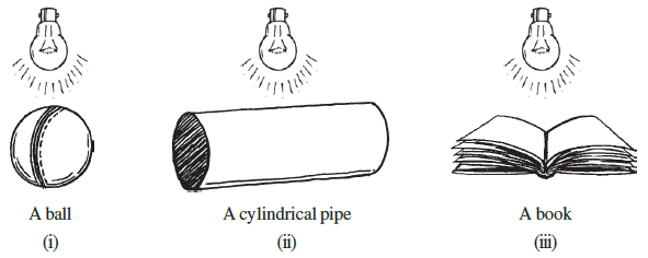
Answer:
The shape of a shadow is the two-dimensional outline of the object that blocks the light. When a light source is placed directly above an object, the shadow cast on the ground will be the shape of the object's top-down view.
(i) A ball
A ball is a sphere in shape. When light shines directly from above, its outline cast on a flat surface is a circle.
Rough Sketch of the Shadow:
(ii) A cylindrical pipe
A cylindrical pipe is a cylinder. When it is placed horizontally and a light source is directly above it, the light is blocked by its rectangular profile. Therefore, the shadow cast will be a rectangle.
Rough Sketch of the Shadow:
(iii) A book
A book is a cuboid. When light shines from directly above, the shadow will take the shape of its top surface. Therefore, the shadow cast by a book is a rectangle.
Rough Sketch of the Shadow:
Here is a summary of the results:
| Object | 3D Shape | Shape of Shadow |
| (i) A ball | Sphere | Circle |
| (ii) A cylindrical pipe | Cylinder | Rectangle |
| (iii) A book | Cuboid | Rectangle |
Question 2. Here are the shadows of some 3-D objects, when seen under the lamp of an overhead projector. Identify the solid(s) that match each shadow. (There may be multiple answers for these!)
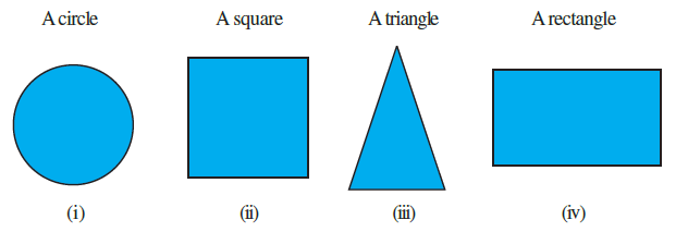
Answer:
The shape of a shadow cast by an overhead projector is the 2D outline of the object as seen from directly above. We need to identify 3D objects that have these specific outlines.
(i) A circle
The following 3D objects can cast a circular shadow:
- A Sphere: A ball or any spherical object will always cast a circular shadow, regardless of its orientation.
- A Cylinder: If a cylinder is standing vertically on one of its circular bases, its top-down view is a circle.
- A Cone: If a cone is standing on its circular base, its top-down view is a circle.
- A Circular Disc: A flat, circular object like a coin or a plate will cast a circular shadow.
(ii) A square
The following 3D objects can cast a square shadow:
- A Cube: A cube will cast a square shadow when one of its faces is parallel to the ground. A die is a common example.
- A Square Pyramid: If a pyramid with a square base is placed on its base, its shadow will be a square.
- A Cuboid with a square face: If a cuboid has a square face and rests on it, the shadow will be a square.
(iii) A triangle
The following 3D objects can cast a triangular shadow:
- A Cone: If a cone is placed lying on its side, its shadow will be a triangle.
- A Triangular Pyramid (Tetrahedron): A pyramid with a triangular base will cast a triangular shadow if it rests on that base.
- A Triangular Prism: If a prism with triangular bases is placed standing on one of its bases, its shadow will be a triangle.
(iv) A rectangle
The following 3D objects can cast a rectangular shadow:
- A Cuboid: A brick or a book is a cuboid, and its top-down view is a rectangle.
- A Cylinder: If a cylinder is placed lying on its side (horizontally), its shadow will be a rectangle.
- A Triangular Prism: If a triangular prism is placed resting on one of its rectangular faces, its shadow will be a rectangle.
The answers can be summarized as follows:
| Shape of Shadow | Possible 3-D Solid(s) |
| (i) A circle | Sphere, Cylinder, Cone, Disc |
| (ii) A square | Cube, Square pyramid |
| (iii) A triangle | Cone, Triangular pyramid, Triangular prism |
| (iv) A rectangle | Cuboid, Cylinder, Triangular prism |
Question 3. Examine if the following are true statements:
(i) The cube can cast a shadow in the shape of a rectangle.
(ii) The cube can cast a shadow in the shape of a hexagon.
Answer:
This question asks us to consider the different 2D shapes that can be formed by the shadow of a 3D cube, depending on the angle of the light source and the orientation of the cube.
(i) The cube can cast a shadow in the shape of a rectangle.
This statement is TRUE.
Explanation:
A shadow is the 2D projection of a 3D object. The simplest way a cube can cast a shadow is when the light source is directly perpendicular to one of its faces. In this case, the shadow cast will be a square.
By definition, a square is a special type of rectangle where all four sides are equal in length. Since a cube can cast a square shadow, and a square is a rectangle, the statement is true.
(ii) The cube can cast a shadow in the shape of a hexagon.
This statement is also TRUE.
Explanation:
A cube can cast a hexagonal shadow under a specific orientation. This happens when the light source is positioned directly in line with a main diagonal of the cube (a line connecting two opposite vertices).
When the cube is held in this position, the outline of the shadow is formed by the six vertices that do not lie on this main diagonal. These six vertices project onto a 2D plane to form a regular hexagon.
